+1 (312)439-2098
- Home
- Solutions
- Residential Buildings
- A Little Smart Home with a Memory Relay
A Little Smart Home with a Memory Relay
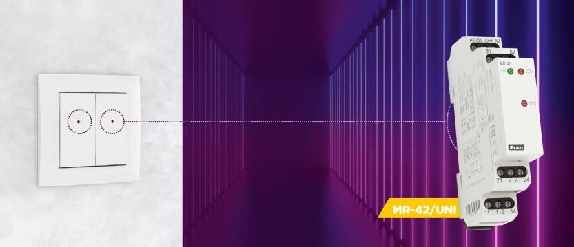
Impulse relays are a great alternative for controlling lighting from multiple locations, but they haven’t fully replaced traditional crossover switch systems. One reason is the added complexity—more devices, more wiring, and higher installation costs. And with the rise of “smart home” systems, their role has diminished further, since most intelligent systems can mimic impulse relay functionality by default.
However, not everyone wants a fully integrated smart home. Sometimes, just a bit of “smartness” is enough to make lighting control more convenient.

The Need for “All On / All Off” Control
Imagine a large open living space—like a kitchen, dining room, and living room combo—equipped with multiple lighting circuits. While these are typically controlled independently, it’s often desirable to also have “All On” and “All Off” buttons to simplify control.
While specialized pulse relays with shared control inputs exist, we’re going to build a more flexible solution using MR-42 relays and some creative logic.
Independent and Group Control Using MR-42
Figure 1 shows a setup using six MR-42 pulse relays—one for each lighting circuit. Unlike standard pushbuttons, we use pushbuttons with changeover contacts (e.g., type 21151 in LOGUS90 design). This allows each circuit to operate independently, while also enabling shared control.
The MR-42 relay provides two independent potential-free changeover contacts. By connecting terminals B1 and B2, we configure the two channels for parallel operation (see Figure 2):
- Channel 1 switches the corresponding light.
- Channel 2 reports the relay’s state to the group control system.

How It Works
Each local pushbutton toggles its assigned MR-42 relay. When idle (not pressed), the local button allows the group control to function.
Here’s the logic:
- Pressing the “All On” button activates only those relays that are currently off.
- Pressing the “All Off” button deactivates only those relays that are currently on.
Because the ON/OFF inputs of the MR-42 work on rising edge detection, the relay state changes only when the control voltage appears, not when it disappears. This ensures stable operation with brief control signals.
The “All On” and “All Off” buttons in the diagram are standard NO pushbuttons from the LOGUS90 21151 series.
Upgrading to One-Button Group Control
If we’re already using pulse relays, wouldn’t it be nice to control everything—including group functions—with a single button?
That’s what the circuit in Figure 3 does.

Components:
- Pushbuttons with changeover contacts remain for individual control.
- A CRM-91H multifunctional time relay provides the required control pulse.
- An MR-41 pulse relay handles group state memory for “on/off” toggling.
When the group control button is pressed, both the “S” input of the time relay and the ON/OFF input of the MR-41 receive the trigger. The MR-41 switches state immediately, but no voltage reaches the relays yet because the CRM-91H output is delayed.
With the time relay set to function “h”, it delays turning on the output for a duration “t,” keeps it on for “t,” then turns it off. This ensures relays don’t toggle too early or overlap unintentionally.
Figure 4 shows the timing diagram.

Two-Wire Solution with Relay Logic
In practice, lighting relays are installed in a central cabinet, with wall-mounted pushbuttons wired back via two wires per button. For the changeover contact logic discussed earlier, three wires would be needed—one more than usual.
To solve this, we simulate the effect of a changeover contact using an auxiliary relay per button, freeing us to use two wires while preserving the same functionality.
However, this comes with trade-offs:
- Do you have space in the cabinet for six more relays?
- Are you okay with the added cost for relays and wiring?
Enter Diode Logic: A Smarter “OR” Control
We’ve previously covered logic operations like AND/OR using mechanical relay contacts. Here, we implement logical OR using diodes—an affordable and compact option, but only suitable for DC circuits.
Figure 5 shows basic diode logic. When one or more diodes conduct (i.e., receive forward voltage), the output is a logical “1”.

Figure 6 applies this logic to pulse relay control:
- All devices are UNI-powered (12–240 V AC/DC).
- For DC use, the A1 terminal must receive the positive voltage.
- Inputs (ON/OFF, S, etc.) detect voltage relative to A1 (GND).
- With no control voltage, the state is held by internal resistance.
Thus, by feeding multiple diode-isolated control signals to a single input, we replicate OR logic—activating a relay regardless of which switch initiated the pulse.

Applying Diode Logic to Six-Circuit Control
Figure 7 shows a complete circuit for six lighting zones with group control via diode logic:
- Devices are powered by 24 V DC, ensuring proper diode operation.
- 1N4007 diodes (or any similar silicon diodes) are used to implement OR logic.
- Diode voltage drop (~0.7 V) is not an issue at 24 V—the MR-42 will still detect a valid control pulse.
MR-42 modules accept input voltages with ±10% tolerance, so 23.3 V is safely within range. While 12 V is also technically allowed, we recommend 24 V DC for reliable operation.

Final Notes
These circuits provide a modular approach to “smart-ish” lighting control using memory relays, time relays, and basic logic components—without needing a full smart home system.
Remember:
- These are conceptual diagrams, subject to adaptation.
- Test and validate circuits for your specific environment.
- Wire colors in diagrams are for clarity only and may not follow standards.
Didn't find what you were looking for?
Technical Support
+1 (312) 439-2098
techsupport@elkoepna.com
Customer Support
+1 (251) 284-6636
elkosupport@elkoepna.com
General Inquiries
+1 (608)746-1332
info@elkoepna.com
Company Headquarters
1150 NW 72nd Ave, Tower I,
Suite 455 #9226, Miami, FL 33126